Guide – How to: design an accelerator in C/C++ (Mentor Catapult HLS)
Latest update: 2020-12-21
This guide illustrates how to design and integrate an accelerator with the ESP high-level synthesis (HLS) flow. The guide uses C++ as the design-specification language and Mentor Catapult HLS as the HLS tool.
Note: This tutorial is self-contained, but the designers should be familiar with the ESP infrastructure and know how to run basic make targets to create a simple instance of ESP that integrates a single core.
Accelerator design
In this guide and in the tutorial material, we design and integrate an accelerator that performs the softmax function for an array of inputs with a fixed-point representation (Mentor ac_fixed). The softmax implementation uses piecewise linear (PWL) approximation and has excellent accuracy. Specifically, for the functionality we leverage an open-source implementation of softmax that Mentor provides. You can find more information at hlslibs.org.
Introduction
In deep learning, the softmax function, is an widely used activation function that turns numbers (logits) into probabilities that sum to one. The softmax function outputs a vector that represents the probability distributions of a list of potential outcomes.
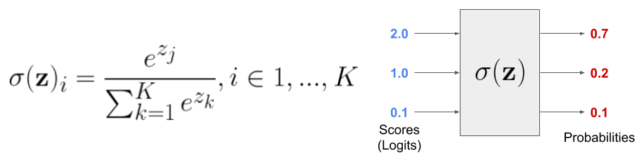
The Mentor implementation of the function ac_softmax_pwl uses the Algorithmic C data types. The input and output arguments of the function are parameterized so that arithmetic may be performed at the desired fixed-point precision and provide a high degree of flexibility on the area/performance trade-off of hardware implementations obtained during Mentor Catapult HLS synthesis.
The integration of the function ac_softmax_pwl in a generic HLS design is relativey easy:
const int num_logits_tb = 20;

typedef ac_fixed<16, 8, true, AC_TRN, AC_SAT> input_type;
typedef ac_fixed<16, 8, false, AC_TRN, AC_SAT> output_type;

#pragma hls_design top
void project(const input_type (&input)[num_logits_tb], output_type (&output)[num_logits_tb]) {
    ac_softmax_pwl(input,output);
}
In this guide, we introduce the users to the design of an accelerator in C++ for Mentor Catapult HLS and its integration in an ESP instance. The focus here is on the accelerator interface and data movement, while we use the ac_softmax_pwl for the computational part of the accelerator. Finally, this guide does not explore the capabilities of the HLS tool for design-space exploration.
Tutorial material
The material helps you run the various steps of this tutorial. Apart from minor edits and console commands, you are not required to explicitly code, but we invite you to review the provided code and scripts as you read the following sections.
The material contains the following code:
- The C++ source code, testbench and Mentor Catapult HLS scripts for the Softmax accelerator (hardware);
- The application and device drivers for the Softmax accelerator (software).
Download and decompress the content of the packet in the ESP root folder <esp>. This guarantees that all of the files are extracted to the right location (see the following section for more details).
cd <esp>/accelerators/catapult_hls
wget https://www.esp.cs.columbia.edu/prebuilt/mentor_cpp_acc/softmax_cxx.tgz
tar xf softmax_cxx.tgz
rm softmax_cxx.tgz
Naming convention and directory structure
We adopt, as a naming convention, the suffix _cxx for the name of accelerators that are designed in C++ with Mentor Catapult HLS. We use _sysc as a suffix for the accelerators that are designed in SystemC. In this case, the name of the accelerator is softmax_cxx.
You should place the source code in specific directories:
- the C++ specification of the accelerator and synthesis scripts for Mentor Catapult HLS in
<esp>/accelerators/catapult_hls/softmax_cxx_catapult/hw; - the software (accelerator’s device driver, bare metal application, and user-space linux application) in
<esp>/accelerators/catapult_hls/softmax_cxx_catapult/sw.
This is a complete list of the files and their locations for the
softmax_cxx accelerator after uncompressing the tutorial
material:
<esp>/accelerators/catapult_hls/softmax_cxx_catapult
├── hw
│   ├── softmax_cxx.xml        # Accelerator description and register list
│   ├── hls                    # HLS scripts
│   │   ├── Makefile
│   │   ├── build_prj.tcl      # Synthesis script
│   │   └── build_prj_top.tcl  # Synthesis script configuration
│   ├── src                    # Accelerator source files
│   │   ├── basic              # Single-block architecture (dir)
│   │   └── hier               # Hierarchical-block architecture (dir)
│   └── tb                     # Testbench
│       └── main.cc
└── sw
    ├── baremetal              # Bare metal test application
    │   ├── softmax_cxx.c
    │   └── Makefile
    └── linux
        ├── app                # Linux test application
        │   ├── cfg.h
        │   ├── softmax_cxx.c
        │   └── Makefile
        ├── driver             # Linux device driver
        │   ├── softmax_cxx_catapult.c
        │   ├── Kbuild
        │   └── Makefile
        └── include
            └── softmax_cxx_catapult.h
Accelerator implementation
The ESP accelerators follow the loosely-coupled model. The accelerators are integrated in an ESP instance as devices managed with Linux device drivers. Loosely-coupled accelerators operate on large data sets and alternate coarse-grain computation with data transfer phases.
The accelerator execution consists of four phases: configure, load, compute, and store. A software application configures the accelerator via memory-mapped registers. The load and store phases interact with the memory controller (DMA) and transfer the data between the external memory and the private local memories (PLMs) of the accelerator. The input PLMs contain the input data, while the output PLMs contain the output data. Additional PLMs may store intermediate results if necessary.
In this guide, we propose two architectures that implement this model: single-block architecture and hierarchical-block architecture. In the single-block architecture, all of the previous phases run in a sequential way and are implemented in a single C++ function. In a hierarchical-block architecture, the phases run concurrently to one another. Adding this type of concurrency can be done by applying HLS constraints in combination with a recommended coding style, while still leaving the C++ untimed and single threaded. The synchronization between blocks is added automatically during the synthesis process.
Accelerator interface
The interface of an ESP accelerator has ports that are common across all of the supported HLS flows as shown in the following figure. There are some minor syntantic sugar differences that are tool dependent.
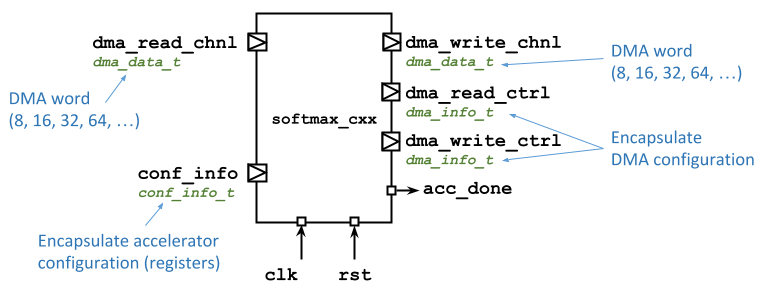
The ports allow the accelerator
- to communicate with the CPU via memory-mapped registers, i.e.
conf_info; - to program the DMA controller, i.e.
dma_read_ctrlanddma_write_ctrl; - to transfer data from and to the main memory, i.e.
dma_read_chnlanddma_write_chnl; - to notify the task completion back to the software application, i.e.
acc_done.
This is the interface of the accelerator for the Mentor Catapult HLS C++ flow:
void softmax_cxx_catapult(
        ac_channel<conf_info_t> &conf_info,
        ac_channel<dma_info_t>  &dma_read_ctrl,
        ac_channel<dma_info_t>  &dma_write_ctrl,
        ac_channel<dma_data_t>  &dma_read_chnl,
        ac_channel<dma_data_t>  &dma_write_chnl,
        ac_sync &acc_done);
These are the TCL directives to define the proper communication protocol at the interface:
directive set /softmax_cxx/conf_info:rsc -MAP_TO_MODULE ccs_ioport.ccs_in_wait
directive set /softmax_cxx/dma_read_ctrl:rsc -MAP_TO_MODULE ccs_ioport.ccs_out_wait
directive set /softmax_cxx/dma_write_ctrl:rsc -MAP_TO_MODULE ccs_ioport.ccs_out_wait
directive set /softmax_cxx/dma_read_chnl:rsc -MAP_TO_MODULE ccs_ioport.ccs_in_wait
directive set /softmax_cxx/dma_write_chnl:rsc -MAP_TO_MODULE ccs_ioport.ccs_out_wait
directive set /softmax_cxx/acc_done:rsc -MAP_TO_MODULE ccs_ioport.ccs_sync_out_vld
The interface relies on
ac_channelcommunication channels to transfer data to/from the top module. This datatype when combined with the HLS directivesccs_ioport.css_in_waitensures that the data is properly synchronized at the interface via a latency-insensitive protocol, i.e. ready-valid-data. When synthesizingac_channel, Mentor Catapult HLS adds the proper handshaking signals to the RTL netlist.ac_syncsynchronization channel that Mentor Catapult HLS offers for specifying standalone handshaking signals when a designer needs to control synchronization directly. It is here combined with theccs_ioport.ccs_sync_out_vldHLS directive.
In addition to the communication and synchronization channels, the accelerator interface relies on the following data types:
- Configuration register that are memory mapped:
struct conf_info_t {
    uint32_t batch;
};
When designing an accelerator, the designer is supposed to add entries to the struct
conf_info_t. We have only one register for our simplesoftmax_cxx. - DMA configuration:
struct dma_info_t {
    uint32_t index;
    uint32_t length;
    ac_int<3, false> size;
};
Where
indexis the memory offset,lengthis the length of the DMA transaction,sizeis an encoding for the DMA width (0for a 8-bit DMA word,1for 16 bits,2for 32 bits, etc.). The designer should not modify the structdma_info_t, which is common to all of the accelerators. - DMA word:
typedef ac_int<DMA_WIDTH, false> dma_data_t;The designer can specify the value for
DMA_WIDTH, which can be 8, 16, 32, 64, 128, etc.
The RTL top module interface from the HLS run is:
module esp_acc_softmax_cxx_struct (
  clk, rst, conf_info_rsc_dat_batch, conf_info_rsc_vld, conf_info_rsc_rdy, dma_read_ctrl_rsc_dat_size,
      dma_read_ctrl_rsc_dat_length, dma_read_ctrl_rsc_dat_index, dma_read_ctrl_rsc_vld,
      dma_read_ctrl_rsc_rdy, dma_write_ctrl_rsc_dat_size, dma_write_ctrl_rsc_dat_length,
      dma_write_ctrl_rsc_dat_index, dma_write_ctrl_rsc_vld, dma_write_ctrl_rsc_rdy,
      dma_read_chnl_rsc_dat, dma_read_chnl_rsc_vld, dma_read_chnl_rsc_rdy, dma_write_chnl_rsc_dat,
      dma_write_chnl_rsc_vld, dma_write_chnl_rsc_rdy, acc_done_rsc_vld
);
  input clk;
  input rst;
  input [31:0] conf_info_rsc_dat_batch;
  input conf_info_rsc_vld;
  output conf_info_rsc_rdy;
  output [2:0] dma_read_ctrl_rsc_dat_size;
  output [31:0] dma_read_ctrl_rsc_dat_length;
  output [31:0] dma_read_ctrl_rsc_dat_index;
  output dma_read_ctrl_rsc_vld;
  input dma_read_ctrl_rsc_rdy;
  output [2:0] dma_write_ctrl_rsc_dat_size;
  output [31:0] dma_write_ctrl_rsc_dat_length;
  output [31:0] dma_write_ctrl_rsc_dat_index;
  output dma_write_ctrl_rsc_vld;
  input dma_write_ctrl_rsc_rdy;
  input [63:0] dma_read_chnl_rsc_dat;
  input dma_read_chnl_rsc_vld;
  output dma_read_chnl_rsc_rdy;
  output [63:0] dma_write_chnl_rsc_dat;
  output dma_write_chnl_rsc_vld;
  input dma_write_chnl_rsc_rdy;
  output acc_done_rsc_vld;

// ...

endmodule
Besides the data channels (suffix _dat), you can notice the additional _rdy and _vld channels to implement latency-insensitive protocols.
Single-block architecture
The main characteristics of the single-block architecture are:
- the configure, load, compute, store phases that run in a sequential way and are implemented in a single C++ function;
- the private local memories (PLMs) that are defined locally to the C++ function.
The pseudo-code for the single-block architecture is:
function softmax_cxx_catapult( /* See Accelerator interface section */)
begin
    // Declare PLMs locally to the function
    data_t plm_in[PLM_SIZE]
    data_t plm_out[PLM_SIZE]

    // Access configuration registers                        //
    regs = conf_info.read()                                  // CONFIGURE PHASE
    batch = regs.batch                                       //

    // Iterate over the load, compute, and store phases
    for (b = 0; b < batch; b++)
    begin
        // Configure the DMA controller for read operations  //
        dma_read_ctrl.write(dma_read_info)                   //
                                                             // LOAD PHASE
        // Now we are ready to read from the main memory     // (DMA-configuration and data-transfer subphases)
        for (r = 0; r < PLM_SIZE; r++)                       //
            plm_in[r] = dma_read_chnl.read()                 //


        // Leverage Mentor Catapult HLS library to perform   //
        // the softmax function                              // COMPUTE PHASE
        ac_math::ac_softmax_pwl(plm_in, plm_out);            //

        // Compute phase is completed, ready to store

        // Configure the DMA controller for write operations //
        dma_write_ctrl.write(dma_write_info)                 //
                                                             // STORE PHASE
        // Now we are ready to write to the main memory      // (DMA-configuration and data-transfer subphases)
        for (w = 0; w < PLM_SIZE; w++)                       //
            dma_write_chnl.write()                           //
    end
end
Notice that it is necessary to explicitely enforce the serialization between DMA-configuration and data-transfer subphases of both the load and compute phases when coding them in C++ for Mentor Catapult HLS. For example, given the previous pseudo code, the following coding style force the serialization between the DMA-configuration and data-transfer subphases of the load phase. The control-data dependency on dma_read_ctrl_done ensures that the data transfer starts only after the DMA configuration has completed. Notice the use of a non-blocking write primitive on the dma_read_ctrl channel. The non-blocking primitive iterates in a loop until it successfully writes to the DMA controller. On success, it returns a true value that goes to the dma_read_ctrl_done flag. The following conditional statement always passes the true branch that encapsulate the data-transfer phase.
dma_read_info = {dma_read_data_index, dma_read_data_length, DMA_SIZE};                            // DMA configuration
bool dma_read_ctrl_done = false;                                                                  // (LOAD PHASE)
do { dma_read_ctrl_done = dma_read_ctrl.nb_write(dma_read_info); } while (!dma_read_ctrl_done);   //


if (dma_read_ctrl_done) { // Force serialization between DMA configuration and data transfer      //
    for (uint16_t i = 0; i < PLM_SIZE; i++) {                                                     // Data transfer
        // pseudo code: plm_in[i] = dma_read_chnl.read()                                          // (LOAD PHASE)
    }                                                                                             //
}                                                                                                 //
The store phase is coded in a similar way:
dma_write_info = {dma_write_data_index, dma_write_data_length, DMA_SIZE};                           // DMA configuration
bool dma_write_ctrl_done = false;                                                                   // (STORE PHASE)
do { dma_write_ctrl_done = dma_write_ctrl.nb_write(dma_write_info); } while (!dma_write_ctrl_done); //

if (dma_write_ctrl_done) { // Force serialization between DMA configuration and data transfer       //
    for (uint16_t i = 0; i < PLM_SIZE; i++) {                                                       // Data transfer
        // pseudo code: dma_write_chnl.write(plm_out[i])                                            // (STORE PHASE)
    }                                                                                               //
}                                                                                                   //
Hierarchical-block architecture
In a hierarchical-block architecture, the ESP-accelerator phases are mapped on blocks that run concurrently to one another. This type of concurrency can be add by applying HLS constraints in combination with a recommended coding style, while still leaving the C++ untimed and single threaded. The synchronization of data flow between blocks is added automatically during the synthesis process.
The main characteristics of the hierarchical-block architecture are:
- the configure, load, compute, store phases are coded as separated C++ functions;
- the private local memories (PLMs) are globally defined and shared among the C++ function.
In common C++ software, functions (e.g. load, compute, and store in this case) can exchange data via shared arrays or variables. However, this becomes problematic for HLS since the synchronization of data exchanged between blocks must be inserted automatically by the synthesis tool. Because of the inherent complexity associated with this, Mentor Catapult HLS offers the modeling construct ac_channel to allow users to directly model the data exchange between blocks of hierarchy.
Note. The user can use the
ac_channelclass library to model both streaming and memory interfaces.
In the top function you can observe
- the declaration of the PLMs which are shared among functions via
ac_channel; - configuration information being exchanged via
ac_channel; - synchronization signals via
ac_sync.
// Encapsulate the PLM array in a templated struct
template <class T, unsigned S>
struct plm_t {
public:
   T data[S];
};

// PLM typedefs
typedef plm_t<FPDATA_IN, PLM_SIZE> plm_in_t;
typedef plm_t<FPDATA_OUT, PLM_SIZE> plm_out_t;

#pragma hls_design top
void CCS_BLOCK(softmax_cxx)(
    ac_channel<conf_info_t> &conf_info,
    ac_channel<dma_info_t> &dma_read_ctrl,
    ac_channel<dma_info_t> &dma_write_ctrl,
    ac_channel<dma_data_t> &dma_read_chnl,
    ac_channel<dma_data_t> &dma_write_chnl,
    ac_sync &acc_done) {

    // Private Local Memories (see typedefs above)
    static ac_channel<plm_in_t> plm_in;
    static ac_channel<plm_out_t> plm_out;

    // Pass configuration information from the configure process/block to the
    // load, compute, and store processes
    static ac_channel<conf_info_t> plm_conf_load;
    static ac_channel<conf_info_t> plm_conf_compute;
    static ac_channel<conf_info_t> plm_conf_store;

    // Block synchronization signals
    static ac_sync config_done;
    static ac_sync load_done;
    static ac_sync compute_done;
    static ac_sync store_done;

    // Configure, load, compute, store processes/blocks
    config(conf_info, plm_conf_load, plm_conf_compute, plm_conf_store, config_done);
    load(plm_conf_load, plm_in, dma_read_ctrl, dma_read_chnl, load_done);
    compute(plm_conf_compute, plm_in, plm_out, compute_done);
    store(plm_conf_store, plm_out, dma_write_ctrl, dma_write_chnl, store_done);

    // Once each process/block has done, it syncs here
    config_done.sync_in();
    load_done.sync_in();
    compute_done.sync_in();
    store_done.sync_in();

    // Accelerator done
    acc_done.sync_out();
}
As array sizes become large, it is typical to map them to memories during synthesis because the area and power costs of mapping to registers becomes prohibitive. In Mentor Catapult HLS, mapping shared arrays between blocks to memories in a hierarchical design results in a ping-pong memory structure automatically inferred. This ping-pong memory structure can consist of two or more memories that are written and read in such an order as to allow the blocks to run concurrently. The following directives map the shared arrays to memories:
directive set /softmax_cxx/core/plm_in.data:rsc -MAP_TO_MODULE Xilinx_RAMS.BLOCK_1R1W_RBW
directive set /softmax_cxx/core/plm_out.data:rsc -MAP_TO_MODULE Xilinx_RAMS.BLOCK_1R1W_RBW
In addition to the above HLS directives, a coding style must be followed to ensure that extra memories are not inadvertently inferred:
- the shared arrays mapped to memories must be packed into a struct (see the code above);
- a local struct with the packed array should be declared to perform the memory operations, this local struct is optimized away if the coding style is followed;
- for example, in the
loadfunction, when you transfer data from the environment via DMA to the shared memoryplm_in(channel), you should declare a local instanceplm_tmpof the structplm_t, iterate over the local instance to read data from the DMA channel, and finally write the local instance intoplm_in:void load( // ... ac_channel< plm_t<FPDATA_IN, PLM_SIZE> > &plm_in, // shared memory over ac_channel // ... ) { // ... // local instance of the memory plm_t<FPDATA_IN, PLM_SIZE> plm_tmp; for (uint16_t i = 0; i < PLM_SIZE; i++) { FPDATA_IN data = dma_read_chnl.read(); plm_tmp.data[i] = data; } // write the local structure on the channel/shared memory plm_in.write(plm_tmp); // ... } - similarly, in the
storefunction, when you transfer data from the local shared memoryplm_out(channel) to the environment via DMA, you should declare a local instanceplm_tmpof the structplm_t, read the entire shared memory into the local instanceplm_tmp, and iterate over the local instance to write data to the DMA channel:void store( // ... ac_channel<plm_out_t> &plm_out, // shared memory over ac_channel // ... ) { // ... // read from the channel/shared memory into a local instance of the memory plm_t<FPDATA_OUT, PLM_SIZE> plm_tmp = plm_out.read(); for (uint16_t i = 0; i < PLM_SIZE; i++) { FPDATA_OUT data = plm_tmp.data[i]; dma_write_chnl.write(data); } // ... } - you should try to only read or write the memory channel once;
- finally, it is also important to limit the scope, or lifetime, of the local struct to avoid inferring extra memories.
Testbench implementation
The testbench code should be at the path accelerators/catapult_hls/softmax_cxx_catapult/hw/tb/.
The testbench for an ESP-accelerator with the C++ flow of Mentor Catapult HLS is fairly simple:
- Keep in mind that the two data-transfer channels
dma_read_chnlanddma_write_chnl, which areac_channel, behave as FIFOs. - The testbench should
- fill
dma_read_chnlfor the load phase (e.g. random data); - pass the values for the configuration registers;
- run the accelerator;
- retrieve the outputs from the
dma_write_chnlfrom the store phase; Finally, note that the testbench should stall until all of data is ready.
- fill
conf_info_t conf_info_data;
conf_info_data.batch = 16;

// DMA-configuration and data-transfer channels
ac_channel<dma_info_t> dma_read_ctrl;
ac_channel<dma_info_t> dma_write_ctrl;
ac_channel<dma_data_t> dma_read_chnl;
ac_channel<dma_data_t> dma_write_chnl;

// Accelerator done
ac_sync acc_done;

for (unsigned i = 0; i < conf_info_data.batch * PLM_SIZE; i++) {
    // Pass inputs to the accelerator via the dam_read_chnl
    FPDATA_IN data = rand();
    dma_read_chnl.write(data);
}

// Pass configuration to the accelerator
conf_info.write(conf_info_data);

// Run the accelerator
softmax_cxx_catapult(conf_info, dma_read_ctrl, dma_write_ctrl, dma_read_chnl, dma_write_chnl, acc_done);

// Fetch outputs from the accelerator
while (!dma_write_chnl.available(conf_info_data.batch * softmax_size)) {} // Testbench stalls until data ready
for (unsigned i = 0; i < conf_info_data.batch * PLM_SIZE; i++) {
    data = dma_write_chnl.read();

    // Run validation
    // ...
}
HLS configuration
The Mentor Catapult HLS scripts should be at the path accelerators/catapult_hls/softmax_cxx_catapult/hw/hls/.
- The script
build_prj_top.tclenables C simulation (csimdefault is1), high-level synthesis (hsynthmust be1), RTL simulation (rtlsimdefault0). Finally, the flaghier- if set to
1, enables the hierarchical-block architecture; - if set to
0, enables the single-block architecture.
- if set to
- Please do not modify
common.tclunless you know what you are doing. This script configure the technology libraries and is shared across the current and future accelerators.
Run HLS
Choose one of the supported boards to create your new SoC instance. For example, in this tutorial we used the Xilinx VCU128 evaluation board, but all instructions are valid for any of the supported boards.
After creating the softmax_cxx accelerator, ESP discovers it in the library of components and generates a set of make targets for it.
# Move to the Xilinx VCU128 working folder
cd <esp>/socs/xilinx-vcu128-xcvu37p

# Run behavioral simulation and HLS with Mentor Catapult HLS
DMA_WIDTH=64 make softmax_cxx_catapult-hls
You can change between single-block and hierarchical-block architecture, by editing <esp>/accelerators/catapult_hls/softmax_cxx_catapult/hw/hls/build_prj_top.tcl and run make softmax_cxx_catapult-hls again.
Accelerator design debug
You can debug an accelerator by executing simulation and synthesis steps directly in the directory <esp>/accelerators/catapult_hls/softmax_cxx_catapult/hw/hls/.
cd accelerators/catapult_hls/softmax_cxx_catapult/hw/hls/
TECH=virtexup ACCELERATOR=softmax_cxx_catapult DMA_WIDTH=64 make hls
Accelerator integration
Target FPGA board
ESP currently supports multiple FPGA boards as listed in the homepage. The <esp>/socs/ directory of ESP contains a working folder for each of the target FPGA boards. The steps described in this guide are identical for all the FPGA targets, but they should be run from the working folder in <esp>/socs/ corresponding to the desired target.
For this tutorial we target the Xilinx VCU128 evaluation board:
# Move to the Xilinx VCU128 working folder
cd <esp>/socs/xilinx-vcu128-xcvu37p
Running make help in the working folder prints a description of the most common Make targets in ESP, many of which are described in this tutorial.
SoC configuration
Each working folder comes with a default SoC configuration (<esp>/socs/defconfig/esp_<working-folder-name>_defconfig), which consists of a 2x2 mesh with one processor tile, one memory tile containing a memory controller and one auxiliary tile. This is the minimum set of tiles for a functioning ESP SoC. Depending on the working folder the default configuration may differ in the processor core selection (e.g. RISC-V Ariane or SparcV8 Leon3) and in the presence of the ESP cache hierarchy.
The SoC configuration can be visualized and modified with the ESP configuration GUI:
make esp-xconfig
At the beginning, the below animated figure shows the GUI with the default configuration for the Xilinx VCU128 board. There is a 2x2 mesh with a memory tile (mem, blue), a CPU tile (cpu, red), an IO tile (IO yellow), and an empty tile. The selected CPU Architecture is the ariane processor.
In order to accommodate two accelerators, you should increase the size of the mesh to 2x3, move the IO tile to a corner, finally, place a softmax_cxx accelerator with single-block (basic_fx32_dma64) and hierarchical-block (hier_fx32_dma64) architecture into the empty tiles, in position (1,0) and (1,1) respectively.
When done, click on the button Generate SoC config and close the window with the button X in the top right corner.
RTL simulation
You can run a full-system RTL simulation of the softmax_cxx accelerator(s) driven by the baremetal application running on the processor tile. Keep in mind that the baremetal simulation is slow, in this case up to 45 minutes. You can edit <esp>/accelerators/catapult_hls/softmax_cxx_catapult/sw/baremetal/softmax_cxx.c to reduce the size of the input array for the softmax_cxx accelerator, and thus to reduce the simulation time.
# Compile baremetal application
make softmax_cxx_catapult-baremetal

# Modelsim
TEST_PROGRAM=./soft-build/ariane/baremetal/softmax_cxx_catapult.exe make sim[-gui]
These simulation targets compile the RTL from ESP and from some Xilinx libraries. In addition to RTL files, the simulation targets cross-compile the baremetal application <esp>/accelerators/catapult_hls/softmax_cxx_catapult/sw/baremetal/softmax_cxx.c for the target processor.
Once Modelsim starts, which is either in the terminal if you run make sim or with a GUI if you run make sim-gui, you can launch the simulation with the command:
vsim> run -all
After the simulation (approx. 45 minutes), you should see the following messages in the console:
[...]
# ahbram0: AHB SRAM Module rev 1, 128 kbytes
# ahbram4: AHB SRAM Module rev 1, 4096 kbytes
# [TRACER] Output filename is: trace_hart_0.log
# ESP-Ariane first-stage boot loader
#
# Scanning device tree...
# [probe] sld,softmax_cxx_catapult.00000000 registered
#         Address   : 0x60011400
#         Interrupt : 00000006
# [probe] sld,softmax_cxx_catapult.00000001 registered
#         Address   : 0x60011500
#         Interrupt : 00000007
# Found 00000002 devices: sld,softmax_cxx_catapult
#   memory buffer base-address = 00000000A0101340
#   ptable = 00000000A0103360
#   nchunk = 00000001
#   Generate input...
#        input  data @00000000A0101340
#   gold output data @00000000A0100330
#   ... input ready!
#   -> Non-coherent DMA
#   Start...
#   Done
#   validating...
#   gold output data @00000000A0100330
#        output data @00000000A0102340
#   total errors 00000000
#   ... PASS                     <---- softmax_cxx - basic_fx32_dma64
#   -> Non-coherent DMA
#   Start...
#   Done
#   validating...
#   gold output data @00000000A0100330
#        output data @00000000A0102340
#   total errors 00000000
#   ... PASS                     <---- softmax_cxx - hier_fx32_dma64
# DONE
# ** Failure: Program Completed! <---- This is not an error, please ignore it.
FPGA prototyping
Note. To continue with the remaining part of the tutorial, you should have setup one of the supported FPGA boards, by connecting it to your working host.
Bitstream generation
The deployment of an ESP SoC on FPGA requires a FPGA bitstream, whereas its testing requires the binary of a baremetal application and/or a Linux image.
Below is the target to generate the FPGA bitstream with Xilinx Vivado from the working folder based on what specified in the ESP configurations. After Vivado completes the bitstream generation, a link to the bitstream top.bit is created in the SoC working folder.
# Logic synthesis for FPGA with Xilinx Vivado
make vivado-syn
Baremetal and Linux applications
We have already seen how to compile a baremetal application:
# Compile baremetal application
make softmax_cxx-baremetal
You can compile and run the corresponding Linux application with:
make linux
This target compiles a Linux kernel and a minimal set of applications for the Linux distribution. Expect a longer runtime.
Note. Make sure not to have setup Mentor Modelsim environment variables in the console where you run the
make linuxbecause the compilation may fail. You can use a separte console.
FPGA programming
Assuming the FPGA host computer is localhost and the TCP port is the default 3121, the ESP instance can be deployed on the FPGA with the following command:
# Program FPGA
FPGA_HOST=localhost XIL_HW_SERVER_PORT=3121 make fpga-program
If you are using a remote FPGA device and the JTAG cable is connected to a remote host computer, set FPGA_HOST and XIL_HW_SERVER_PORT to the appropriate values. The remote server must be running an instance of Vivado hw_server.
UART interface
After programming the FPGA, the ESP UART interface must be opened with a serial communication program (e.g. minicom) to monitor the programs executing on the ESP instance.
With the USB cable provided by the FPGA board vendor, connect the UART port to any USB port on your computer. Then run dmesg to find the device name assigned to the new serial interface. Here is an example:
$ dmesg | grep tty
[352854.825049] usb 1-2: cp210x converter now attached to ttyUSB0
For instance, if your serial interface has been labeled ttyUSB0, you may connect to /dev/ttyUSB0 with your favorite serial communication program. In this example we refer to Minicom. The serial interface should be configured to use no parity bits, no flow control and a baud rate of 38400. To configure Minicom launch it with sudo minicom -s.
 +-----------------------------------------+
 |     Serial Device      : /dev/ttyUSB0   |
 |  Lockfile Location     : /var/lock      |
 |    Callin Program      :                |
 |   Callout Program      :                |
 |     Bps/Par/Bits       : 38400 8N1      |
 |  Hardware Flow Control : No             |
 |  Software Flow Control : No             |
 +-----------------------------------------+
Now you can launch Minicom:
minicom -D /dev/ttyUSB0 -b 38400
Please note that standard users on Linux do not have permission to connect to a serial interface. You can launch your terminal with sudo, or add yourself to the dialout group. Then you must log out in order for the group change to take effect.
sudo usermod -aG dialout <USERNAME>
Testing on FPGA (baremetal)
On the SoC running on the FPGA without Linux OS (baremetal), you can execute the same application that you previously executed in simulation.
Once you have the FPGA programmed and you have an active Minicom console, run the bare-metal program in the working directory:
# Run baremetal program (./soft-build/ariane/baremetal/softmax_cxx_catapult.exe)
TEST_PROGRAM=./soft-build/ariane/baremetal/softmax_cxx_catapult.exe make fpga-run
Now you should check the Minicom console and see:
# ESP-Ariane first-stage boot loader

Scanning device tree...
[probe] sld,softmax_cxx_catapult.00000000 registered
        Address   : 0x60011400
        Interrupt : 00000006
[probe] sld,softmax_cxx_catapult.00000001 registered
        Address   : 0x60011500
        Interrupt : 00000007
Found 00000002 devices: sld,softmax_cxx_catapult
  memory buffer base-address = 00000000A0101340
  ptable = 00000000A0103360
  nchunk = 00000001
  Generate input...
       input  data @00000000A0101340
  gold output data @00000000A0100330
  ... input ready!
  -> Non-coherent DMA
  Start...
  Done
  validating...
  gold output data @00000000A0100330
       output data @00000000A0102340
  total errors 00000000
  ... PASS
  -> Non-coherent DMA
  Start...
  Done
  validating...
  gold output data @00000000A0100330
       output data @00000000A0102340
  total errors 00000000
  ... PASS
DONE
Testing on FPGA (with Linux OS)
Once you have the FPGA programmed and you have an active Minicom console, run the testing application in the working directory:
# Run Linux (linux.bin)
FPGA_HOST=localhost XIL_HW_SERVER_PORT=3121 make fpga-run-linux
Now you should check the Minicom console and see the operating system booting. Once the boot is complete, to login into Linux use root as username and openesp as password. The latter is set by buildroot when the template for the root file system is generated (see setup).
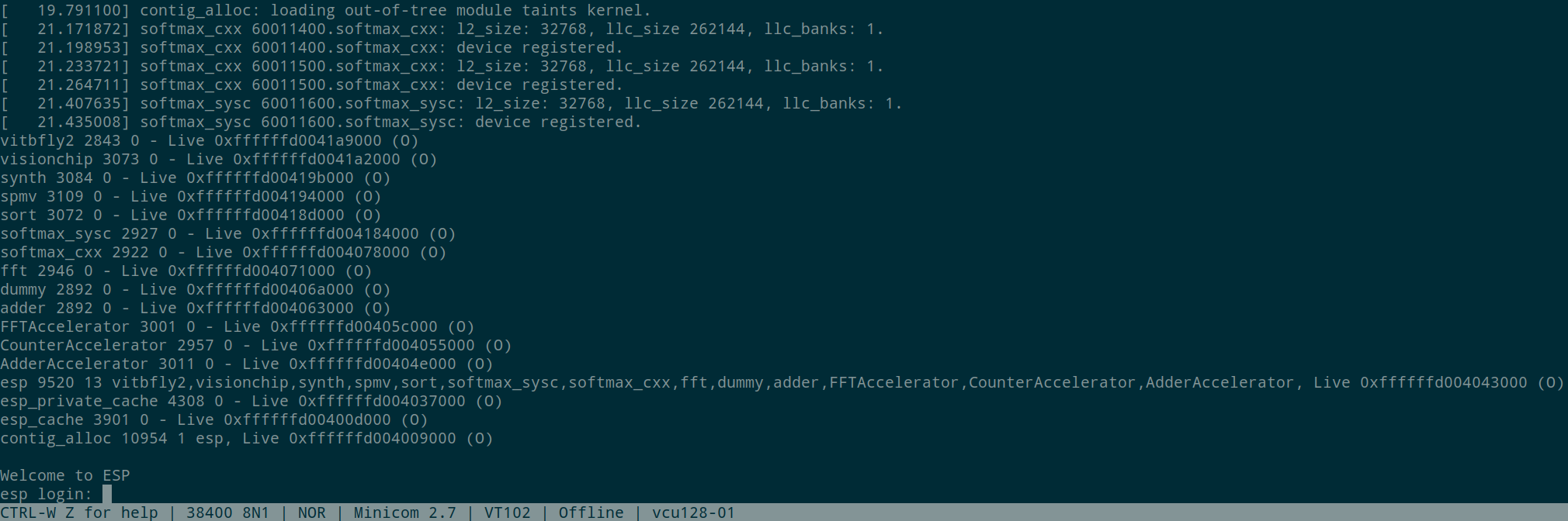
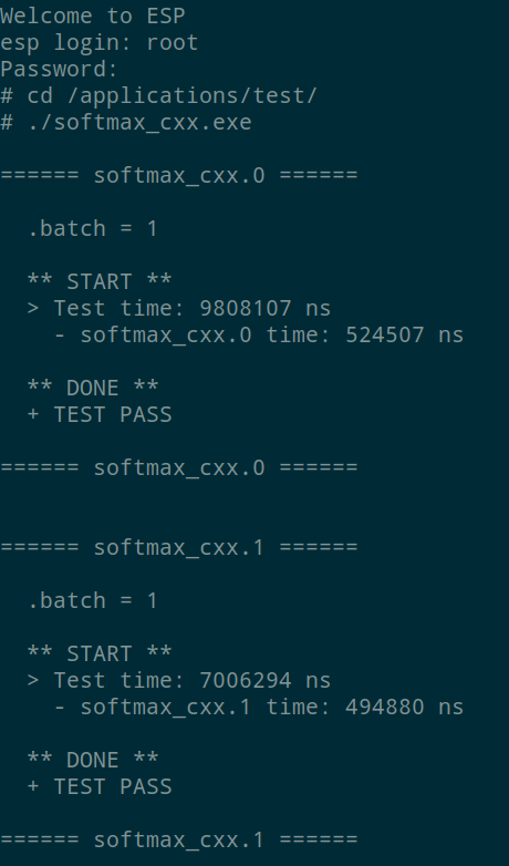
To execute the Linux application for softmax_cxx:
$ cd /applications/test/
$ ./softmax_cxx_catapult.exe
On the console you should see:
SSH on Linux OS running on ESP/FPGA
Once Linux boot has completed, it is possible to use SSH to access ESP remotely, as well as to move data to and from the ESP SoC on FPGA.
The IP address is printed on the serial console at the end of the boot process: udhcpc: lease of <esp-ip-address> obtained. Alternatively, you can get the network interface configuration and IP address with ifconfig
From a machine in the same network as the ESP instance on FPGA, you can use ssh or scp and pass the dynamic IP leased at the end of the Linux boot.
touch file_to_transfer
scp file_to_transfer root@<esp-ip-address>:~
ssh root@<esp-ip-address>
From the ESP Linux terminal you can use ssh and scp commands as in these examples:
touch file_to_transfer
ssh <username>@<host-static-ip>
scp file_to_transfer <username>@<host-static-ip>:~